LED technology is taking leaps and bounds. Did anyone imagine 10-20 years ago that a tiny semiconductor crystal would be able to illuminate a considerable area, while consuming only a few watts? So I decided to change the lighting in the apartment to LED.
In many places I had halogen lamps with lamps under the GU10 cartridge. To replace them, I bought Gauss EB101006125 2.5 W LED light bulbs. Thus, the entrance hall, corridor, bathroom, toilet and hood in the kitchen were provided with LEDs.
There were still furniture lamps under the G4 cartridge with halogen lamps with a power of 20 W in the visor above the kitchen set. No matter how much I searched in the shops and in the market — I found nothing. I decided to make the lamps myself: I picked up the appropriate parts on the Internet and made an order.
Just a few days later, he was at my house: white light LEDs of two types 3HPD-1 (W=1 W, Φν=110-120 lm, 2Q1 / 2=120°, T=3100 K) and 3HPD-3 (W=3 W, Φν=250-270 lm, 2Q1/2=120°, T=3060 K). And to them –hot glue, round mounting panels, drivers for power supply and an aluminum sheet with a thickness of 0.8 mm for radiators.
Radiator plates
First of all, I disassembled the lamps (photo 1), measured the diameter of the glass (in its place there should have been a plate with an LED pasted on it) and started working on the radiator plates. I drew an aluminum sheet and used scissors to cut out the squares first, and then the radiators. (photo 2). With a file, I gave them the final shape (photo 3).
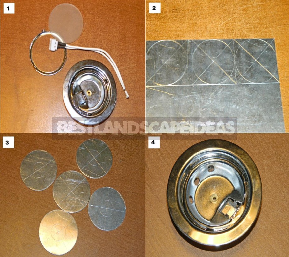
Then I modified the lamps: I drilled three holes of Ø6 mm in the reflectors for air convection and cut off the upper mounting pad of the G4 cartridge with a hand drill with a cutting disc. As a result, the lamp was fully prepared for the installation of the radiator (photo 4). It remains a small matter-to stick the LEDs on the mounting panels, and those on the radiators, solder everything and assemble the lamps.
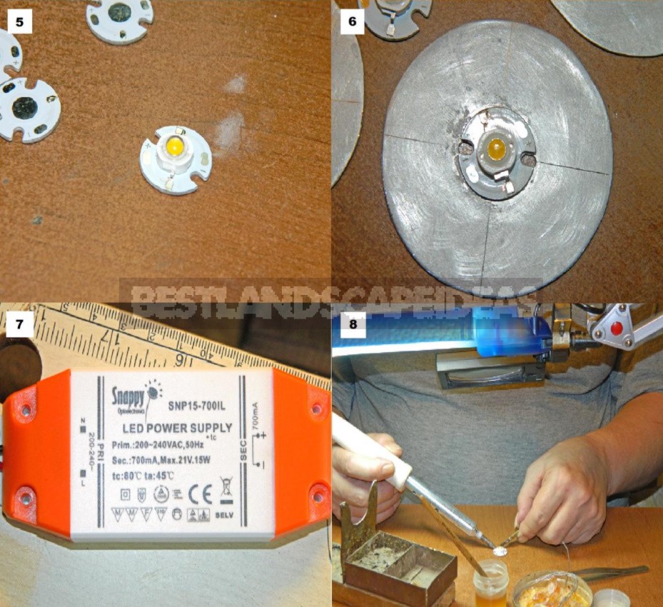
The panel is a multi-layer disk Ø16 mm with a central heat sink pad and contacts for soldering the LED pins and lead wires. I applied a thin layer of glue to the pad, then put the LED (photo 5). After 15-20 minutes, when the glue gripped, I glued the mounting plate to the radiator (photo 6).
Driver
While the glue was drying (and this is 24 hours), I decided to do the electrical part. For LEDs, the current flowing through them is very important. Therefore, they use current sources called PWM drivers to power them. To power 5 3 W LEDs connected in series, I used a 700 mA device (photo 7) with the following characteristics:
- Input voltage-AC 180-264 V;
- EFFICIENCY — 86%;
- power factor-0.85-0.9;
- Output voltage-18-21 V;
- Output current-700 mA;
- Peak current — 740 mA (500 nS);
- Operating temperature – -20°C to +45°C.
With this driver, when the voltage drop on the LED is 2.9-3.7 V, each of them should produce a luminous flux of at least 240-250 lm, which is 1.8-2.0 times higher than the flux of a 20-Watt halogen light bulb.
With the LED connection loop, everything is simple – I used a double wire for connecting audio speakers with a cross section of 0.75 mm and ordinary screw terminal blocks.
Installation of LEDs and wires
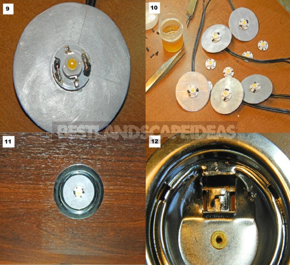
Then there was a difficult and painstaking work – to solder small LEDs to the mounting plate and connection wire pads. A lamp with a magnifying glass and a flux — rosin diluted in alcohol helped out (photo 8). As a result, I carefully soldered all five radiating elements (photos 9-10). As the lead wires, I used a cable for speakers with a cross section of 0.5 mm.
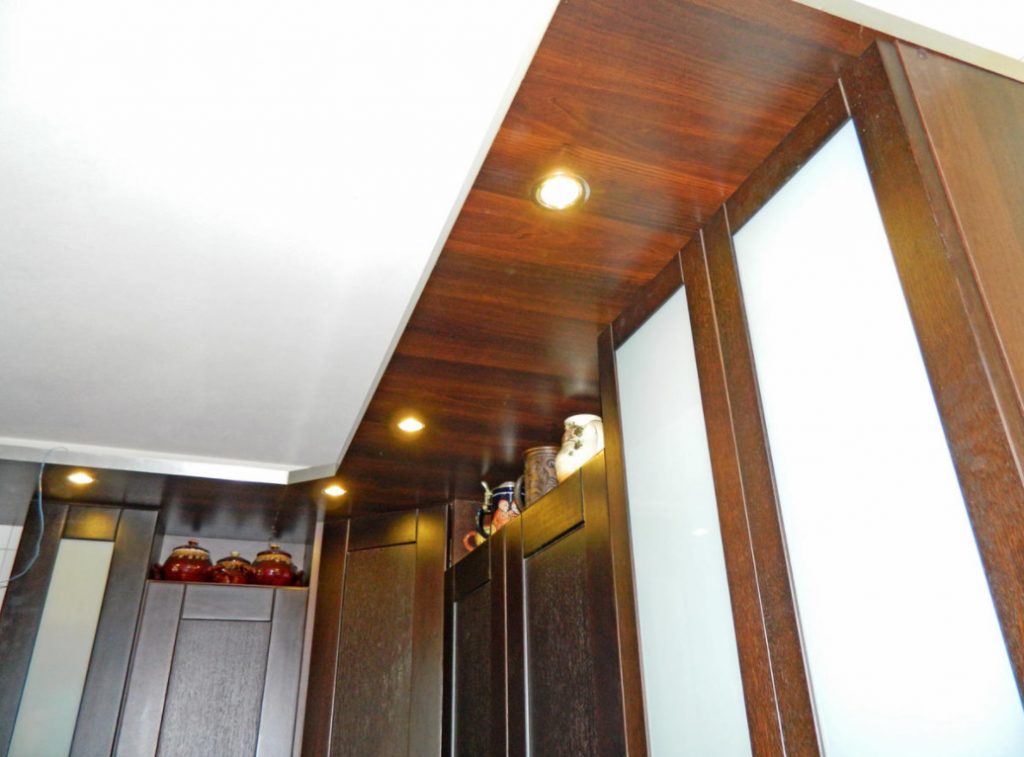
Now it remained to assemble the lamps, insert them into the sockets in the kitchen canopy, connect the driver and perform a health check (photo 11). The test showed that the LEDs outperform the halogens in terms of illumination, significantly saving electricity (instead of 100 Watts — only 15!). But one thing I did not take into account – the LED lamp protruded 8-10 mm and did not allow the doors of the hanging shelves to open!
Final assembly of the backlight
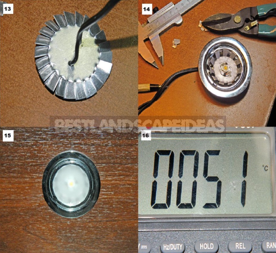
I had to redo everything. I disassembled the lamps and prepared them so that I could sink the radiators in them. To do this, I bent the limiter plates and tapped the reflector with a hammer (photo 12). Then I made cuts on the radiator plate to a depth of 8 mm, and calculated everything so that the petals turned out to be an odd number (photo 13). Then the “platypus” broke through one of the petals and bent the remaining ones in the form of a light reflector in the lamp (photo 14).
After assembling the lamp, it turned out that the radiator falls out of it, so I had to put the “native” frosted glass (photo 15). What’s wrong with that? First, the area of the radiator has decreased, and, consequently, the cooling of the LED has been disrupted. Secondly, one surface of the radiator, which is under the glass, is poorly cooled. All this can lead to the fact that the LED will overheat and quickly degrade. In general, the loss of luminous flux due to the installation of glass was 12-15% — this is not the worst thing.
Everything works!
Measurements on the back of the radiator showed that in the first 10 minutes the temperature increases to 45°-48°C (measurements were carried out with a VC97 multimeter). Then, within an hour, it slowly rises to 55°-58°C, then decreases to 51°C and stabilizes (photo 16).
The maximum transition temperature for LEDs of this type should not exceed 120-130°C, and therefore the radiator can heat up to 60-65°C (reference data). The luminous flux has dropped to 200-210 lm, but the light from five lamps is more than enough!
